Drawer Box
- Upcut Saw Instruction Procedure
- Lock Dowel Drawer Box Instruction Procedure
- Dovetail Jointer Instruction Procedure
Upcut Saw Instruction Procedure
Purpose
Using the Upcut saw will provide you with digital accuracy and a cleaner and smoother cut
Powering on Machine
|
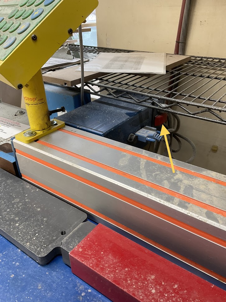
1. Turn on the control panel by pressing the red switch located on the right side of the blue electrical box behind the control panel |
 |
|
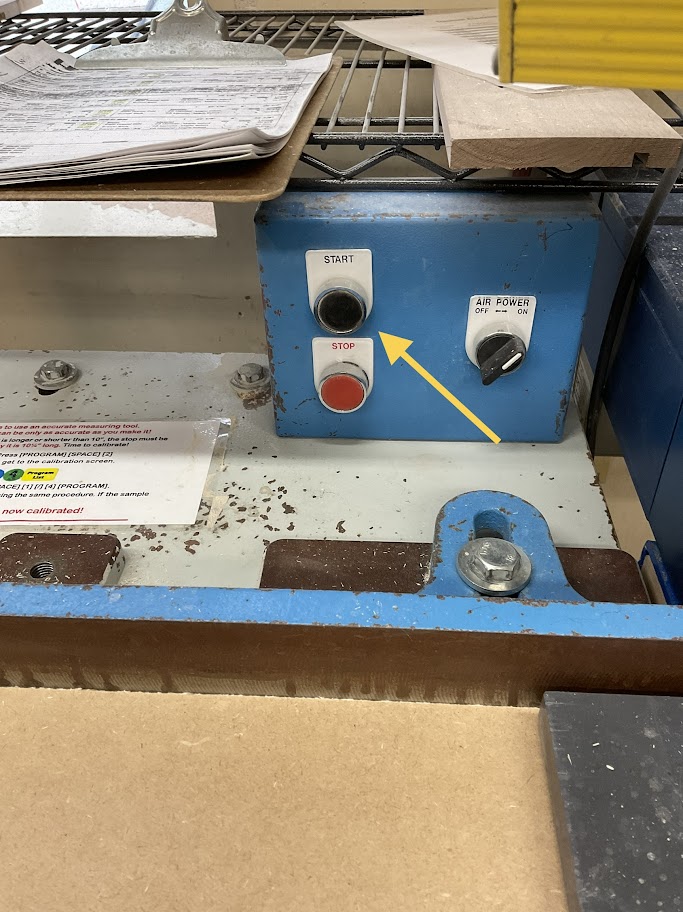
2. Turn on the saw by pressing the black start button located on the blue electrical box located left of the control panel |
 |
Calibrating Machine
3. On the control panel Press ("Program List", "Space Calib",2) This will bring up the calibration screen
4. Enter 1, 0, "Space Calib", 1, /, 4, "Program List"
Steps 3 and 4 only need to be done in the morning before the shift starts
Running Machine
5. Using the decimal equivalents enter your length to be cut
For example if your length is 12 1/2 inches you will enter 12.
6. Press "Start"
|
7. Measure the length of damage on the board to be cut |
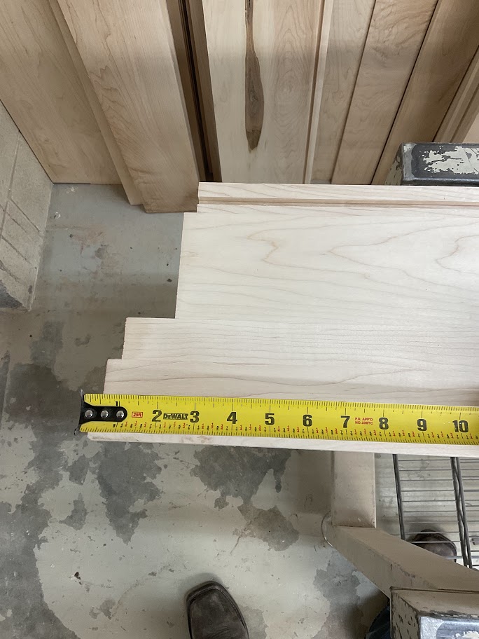 |
8. Press "+", enter the damaged length the press "=" then press the "Start" button
For example our desired length is 12.5 inches and we have 4 inches of damage this step will make your cut length 16.5 inches
|
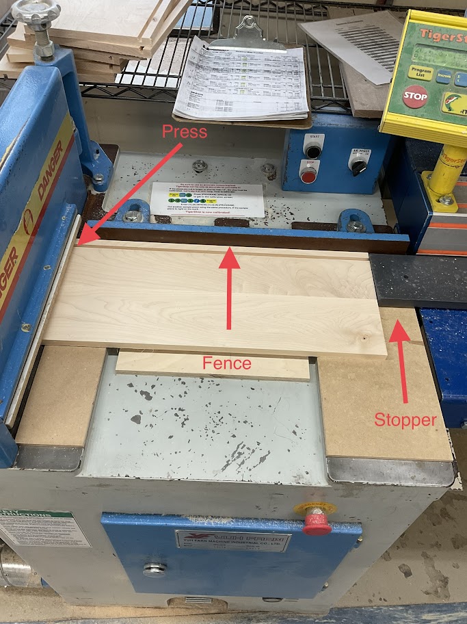
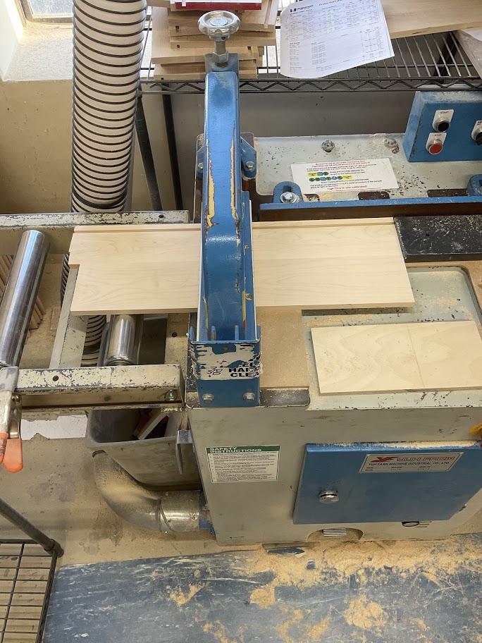
9. Run your board through the press, flat against the fence to the stopper |
 |
|
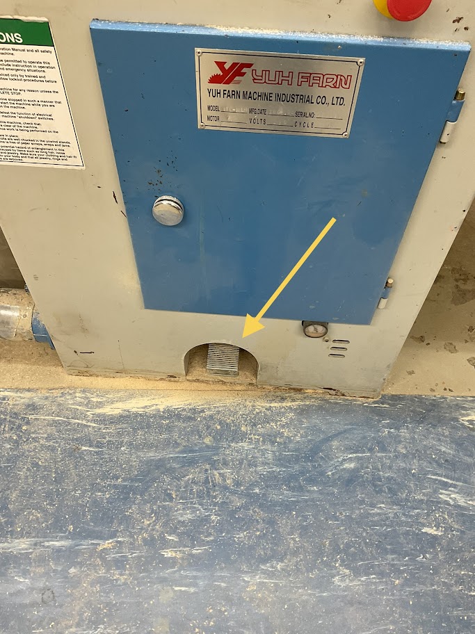
10. Once the board is in place press the foot pedal located below the machine |
 |
11. When the board is cut press "-", re-enter the damaged length then "=" then the "Start" button
This step will take off the 4 inches you added and put you back to your desired 12.5 inches
|
12. Rotate the board where the damaged length is out and then press the foot pedal to cut off the damaged length |
 |
Note that steps 3, 4, and 7 are only needed when cutting a new board
Powering off Machine
|
13. Turn off the saw by pressing the red stop button on the blue electrical box located left of the control panel |
 |
|
14. Turn off the control panel by pressing the red switch located on the right side of the blue electrical box behind the control panel |
 |
Lock Dowel Drawer Box Instruction Procedure
Purpose
Lock dowels are used to create a clean non fastener look for melamine boxes
Drawer Box Assembly
|
1. Gather all your parts by reading the labels Labels will be coordinated with a number in the top right corner with Left, Right, Front, Back, and Bottom |
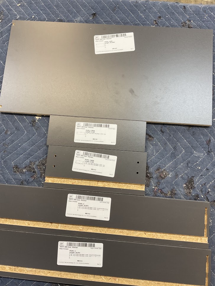 |
2. Inspect all your parts for imperfections before starting
If imperfections are found, show them to your supervisor and they will direct you to the proper method to fix it or instruct you to have the part recut
|
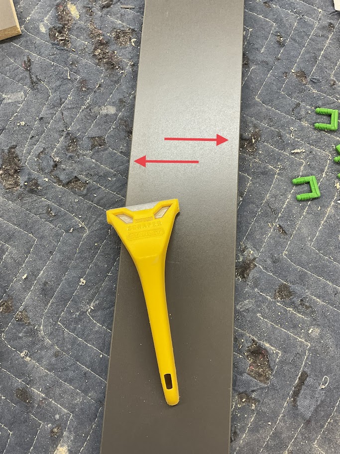
3. Using the proper tool, clean the edges of each part of any glue or hang over |
 |
|
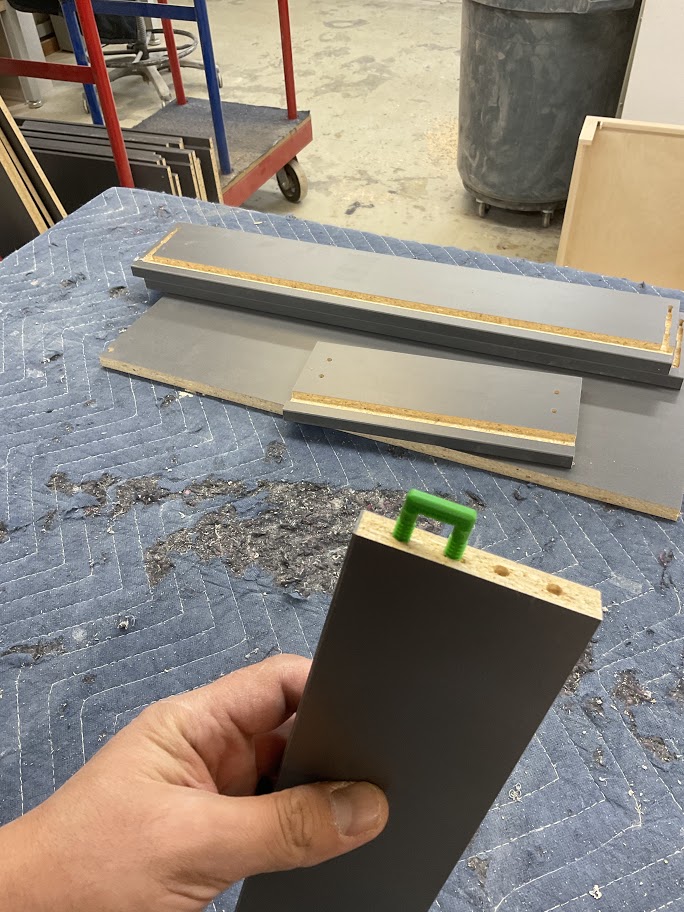
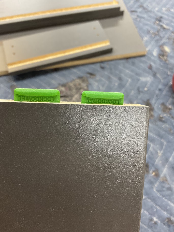
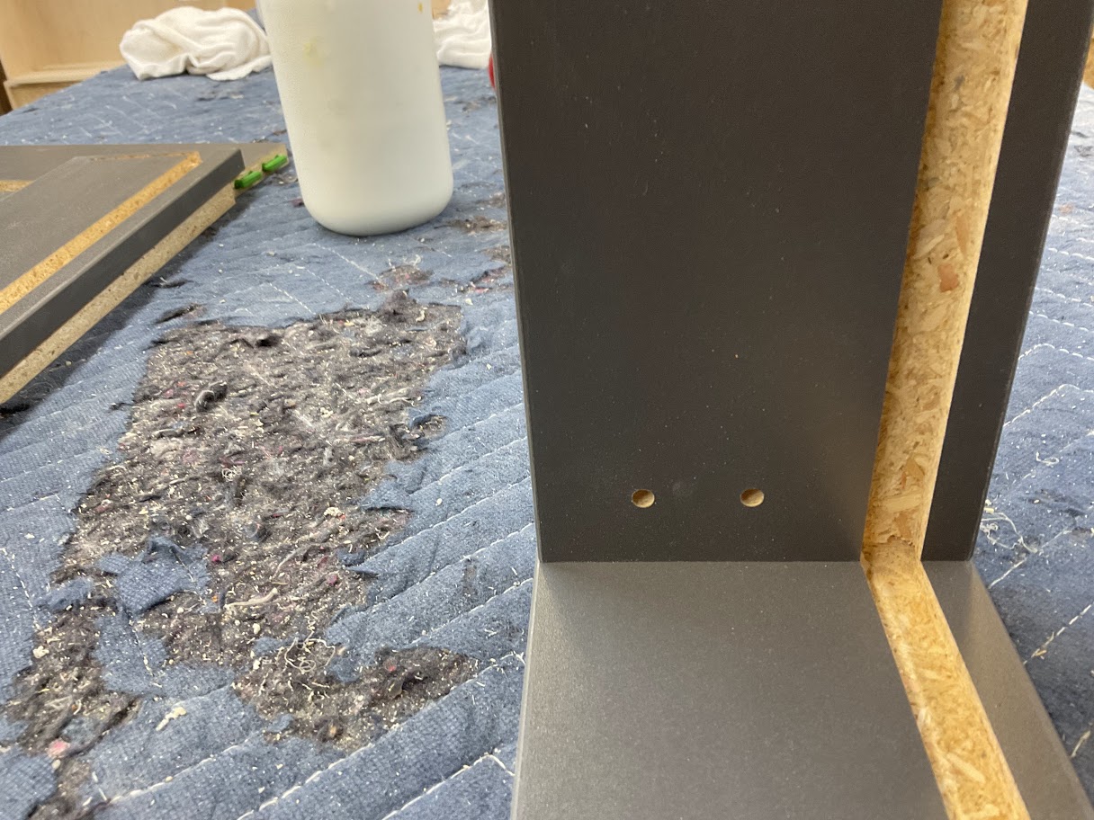
4. Place lock dowels in the designated per drilled holes |
 |
|
5. Using a soft mallet, lightly tap the lock dowel down till the bottom of the dowel is flush with part |
 |
|
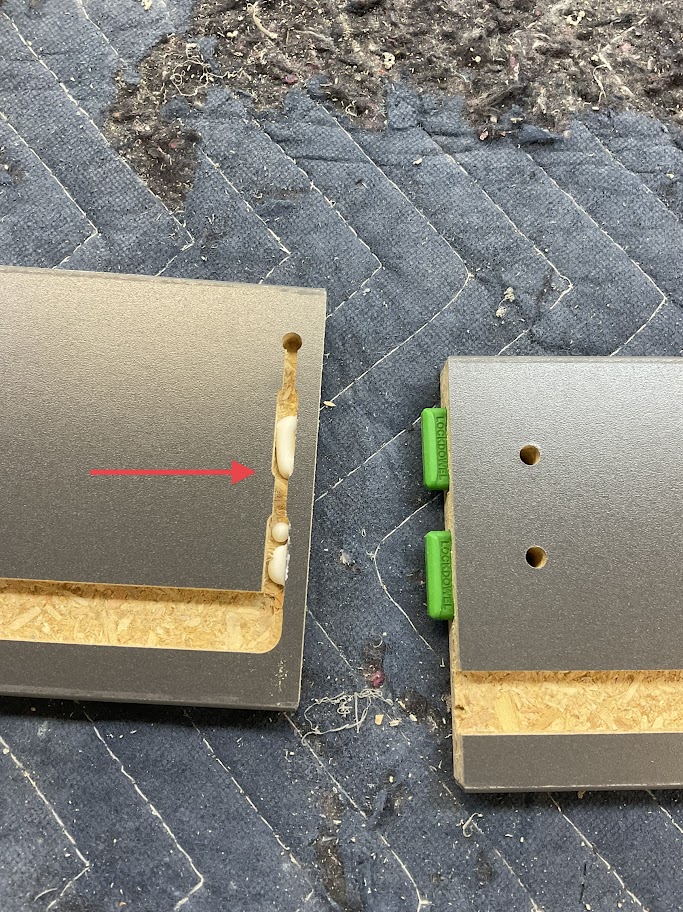
6. Place glue in the coordinating keyhole slots |
 |
|
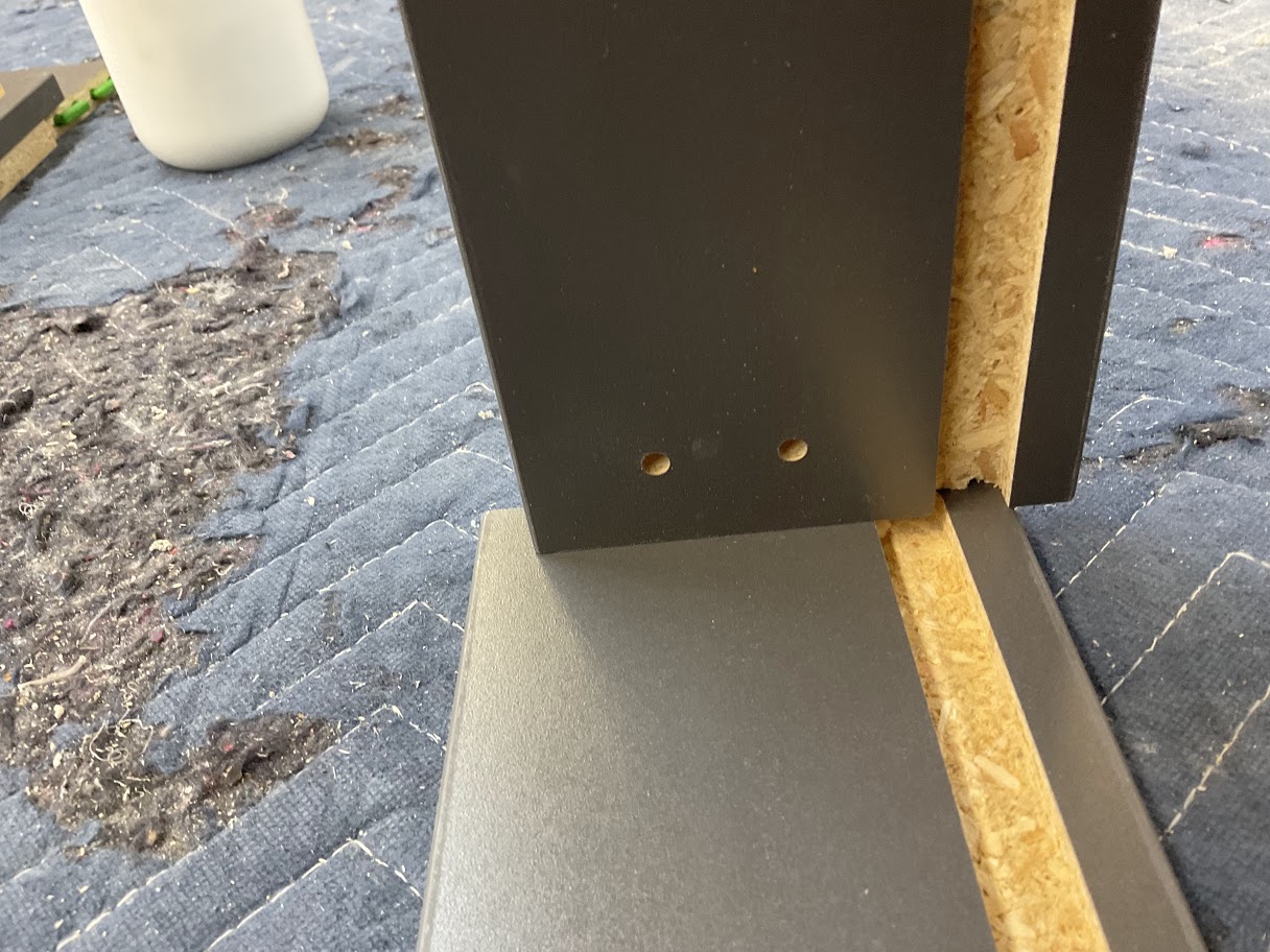
7. Insert the Lock Dowell into the coordinating keyhole slot to create the locking mechanism |
 |
|
8. Push the part up to lock in place |
 |
|
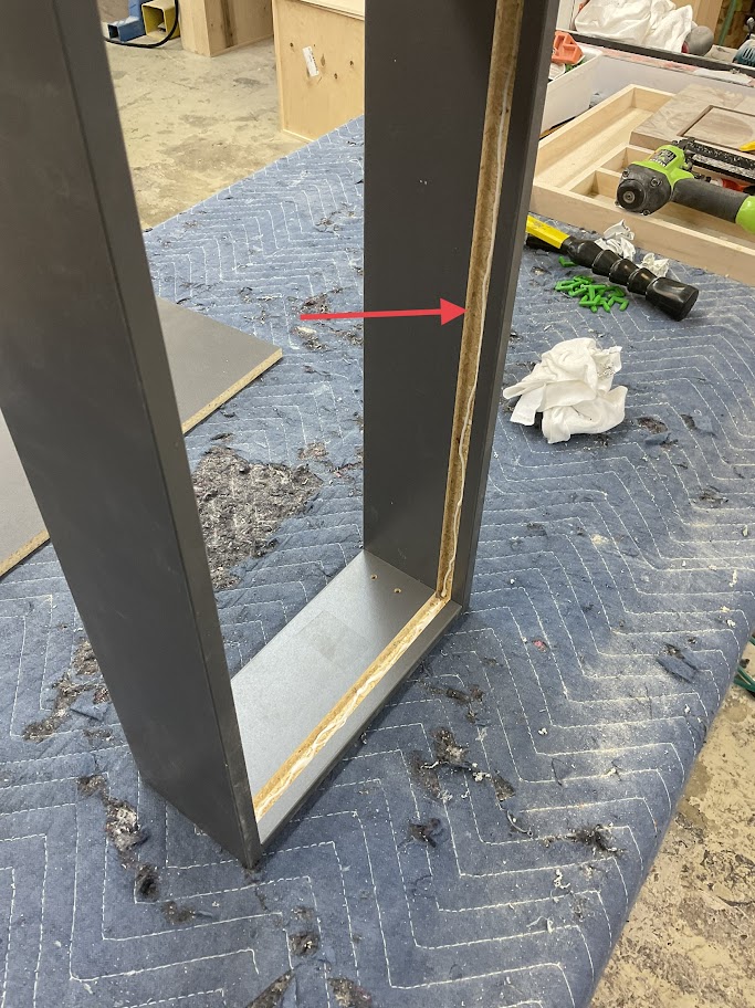
9. Place glue in the dado that the drawer box bottom will be placed |
 |
|
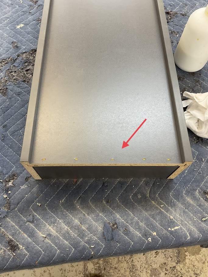
10. With the glide holes up and facing toward the inside of the box, slide the bottom into the bottoms' dado |
 |
|
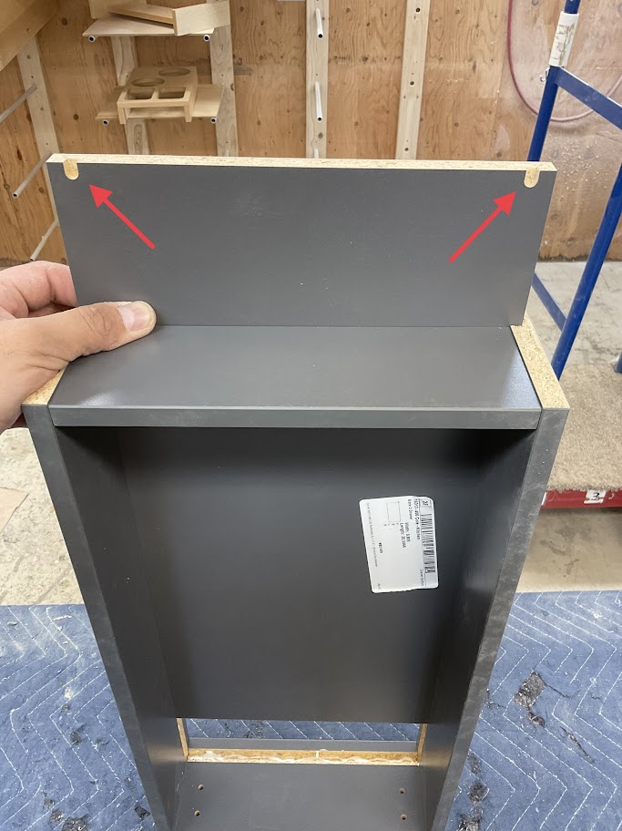
11. Make sure the bottom is flush with the back |
 |
|
12. Using a staple gun and the 1 1/4" staples secure the bottom to the back panel |
 |
13. Put fastcaps over drawer front screw holes to prevent cracking
Dovetail Jointer Instruction Procedure
Purpose
Dovetail joints make the drawer box stronger while still giving it a classier look
Powering Up Machine
|
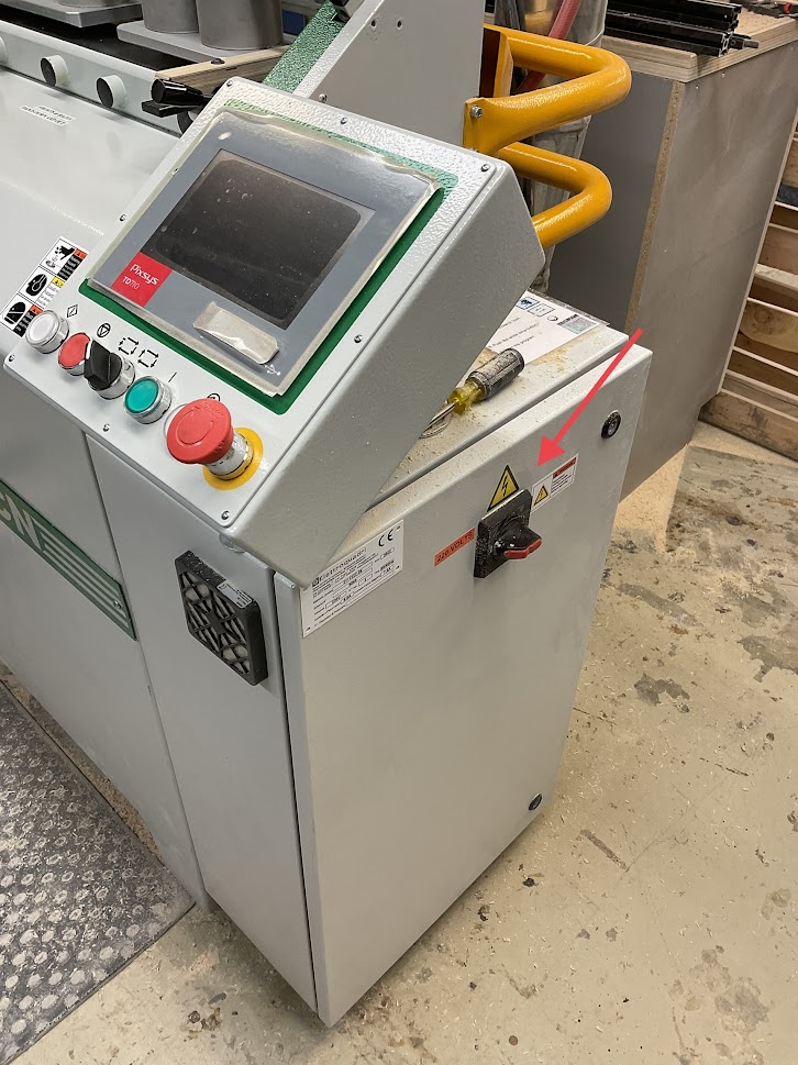
1. Turn the switch to the on position, located on the right side of the machine |
 |
|
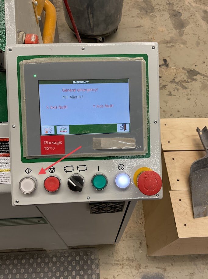
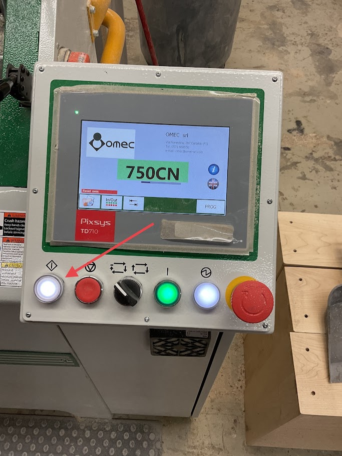
2. Press the white button on the left of the control panel |
 |
|
3. Press the green button on the right of the control panel |
 |
|
4. Press the open door icon located on the lower right side of the screen |
 |
|
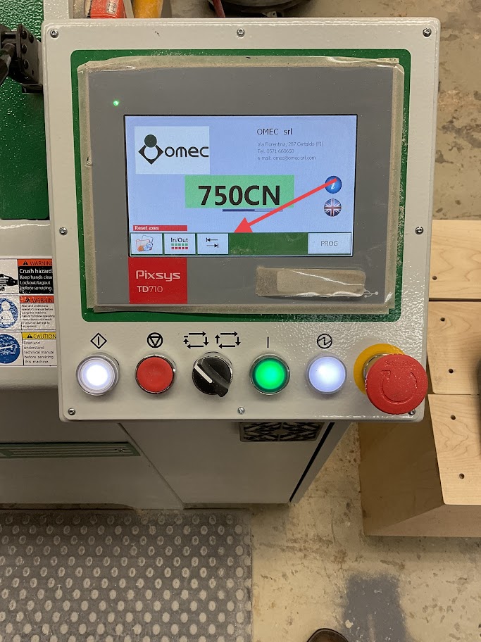
5. Press the Zero Research icon on the lower left side of the screen |
 |
|
6. Press the white button on the left of the control panel |
 |
|
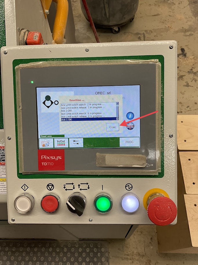
7. When the reset is complete press the close icon on the screen |
 |
|
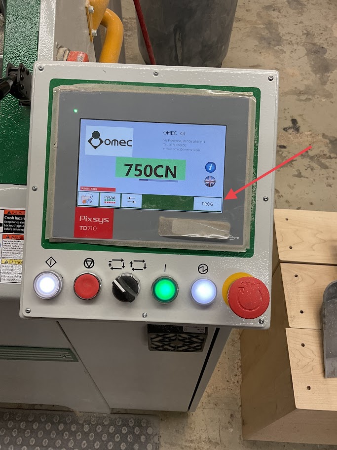
8. Press "PROG" icon on the lower right of the screen |
 |
|
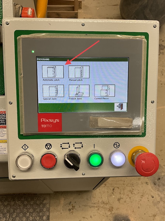
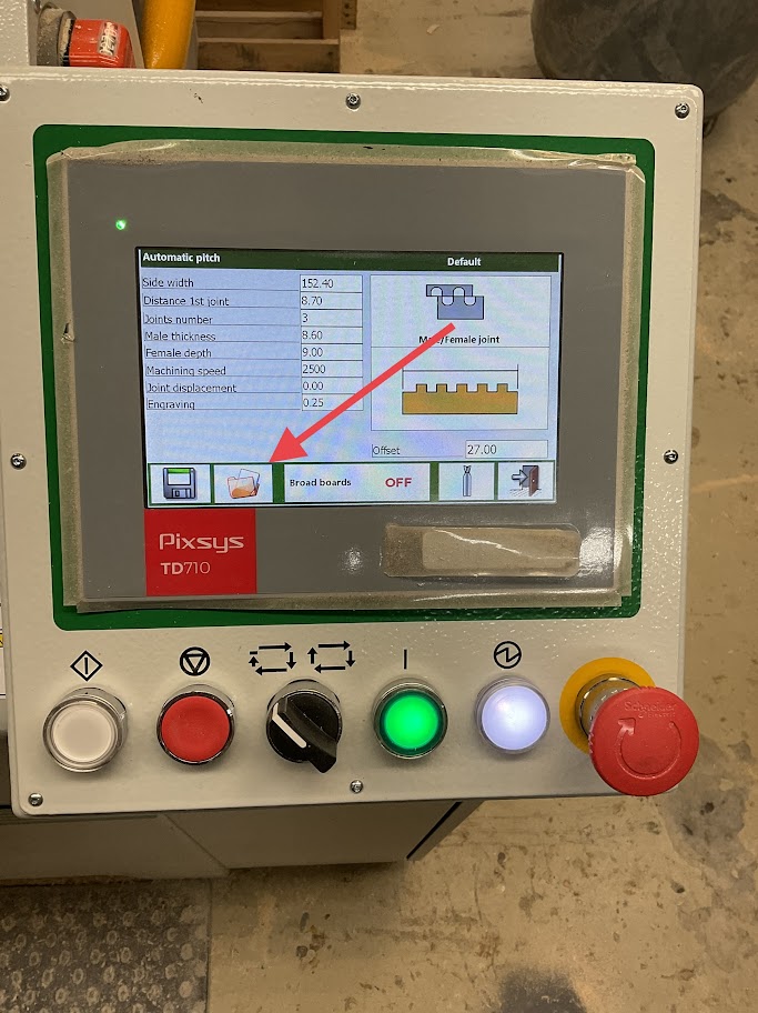
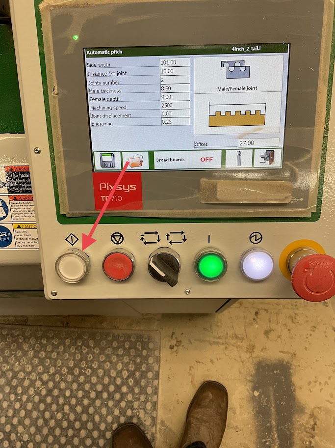
9. Select the "Automatic Pitch" icon on the upper left of the screen |
 |
Milling Set Up
|
10. Press the Folder icon on the lower left of the screen |
 |
|
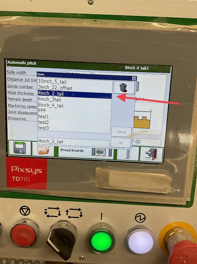
11. Select the file for the width of the board you will be milling For example, if the board width is 4 inch select the "4inch" file |
 |
Milling Board
|
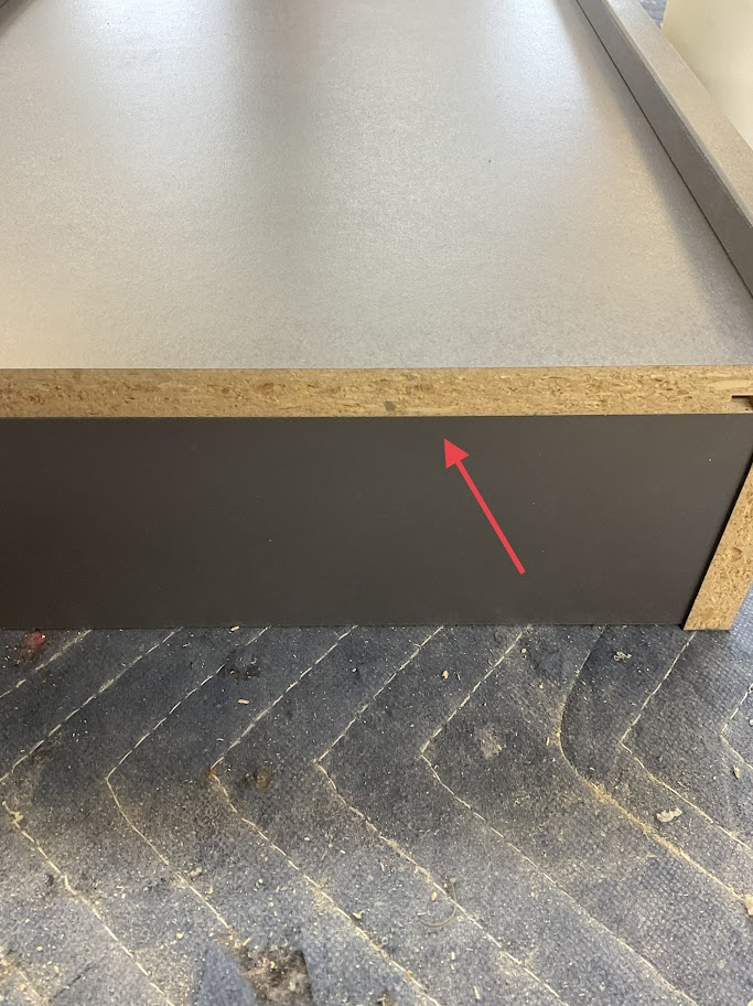
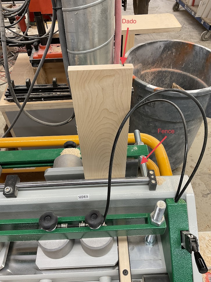
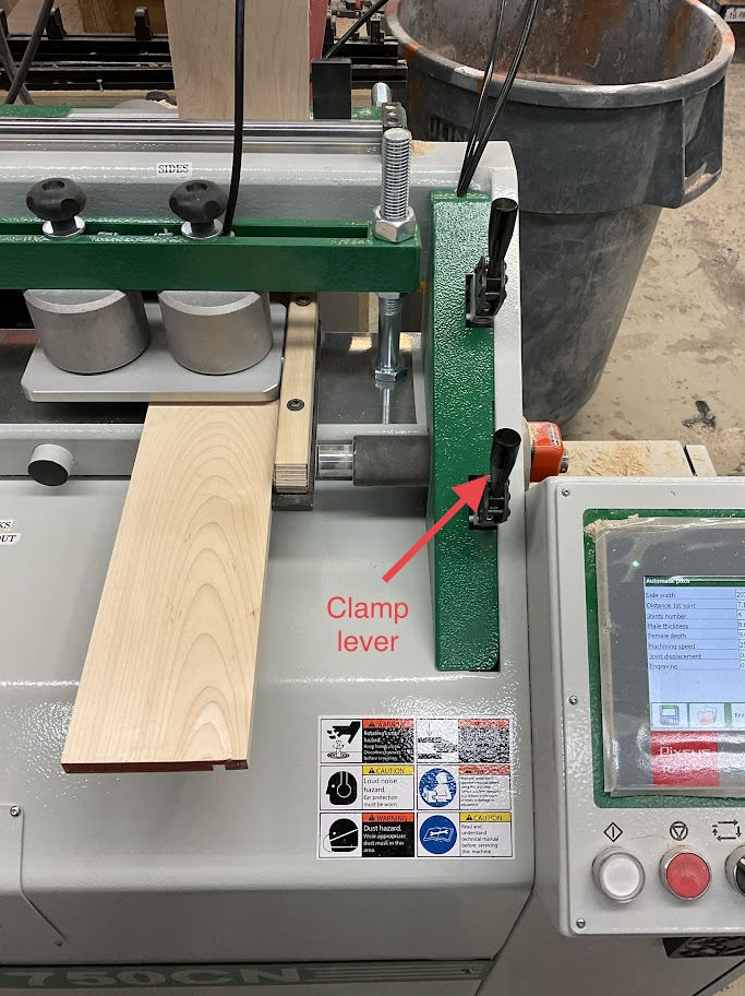
12. Place your side board in first with your panel being upright with the dado facing out and away flush against the fence |
 |
|
13. Push the clamp lever forward to secure the board in place |
 |
|
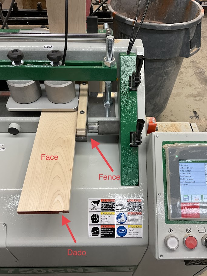
14. Place your front or back board face up with the dado down and away flush against the side panel and flush against the fence |
 |
|
15. Push the clamp lever forward to secure the board in place |
 |
|
16. Once all boards are in place and secured press the white button on the left side of the control panel to start the milling process. Repeat these steps for the left side. Make sure to look up in the right side of the screen to make sure the correct file is selected for the board size that is going to be dovetailed |
 |
|
17. Note, make sure that the "Broad Boards" icon is set to the side that the board will be milled. If boards are set on both sides made sure the "Broad Boards" icon says OFF |
 |
Powering off Machine
|
18. Simply turn the power switch in the off position, Located on the right side of the machine
|
 |